
Hi there
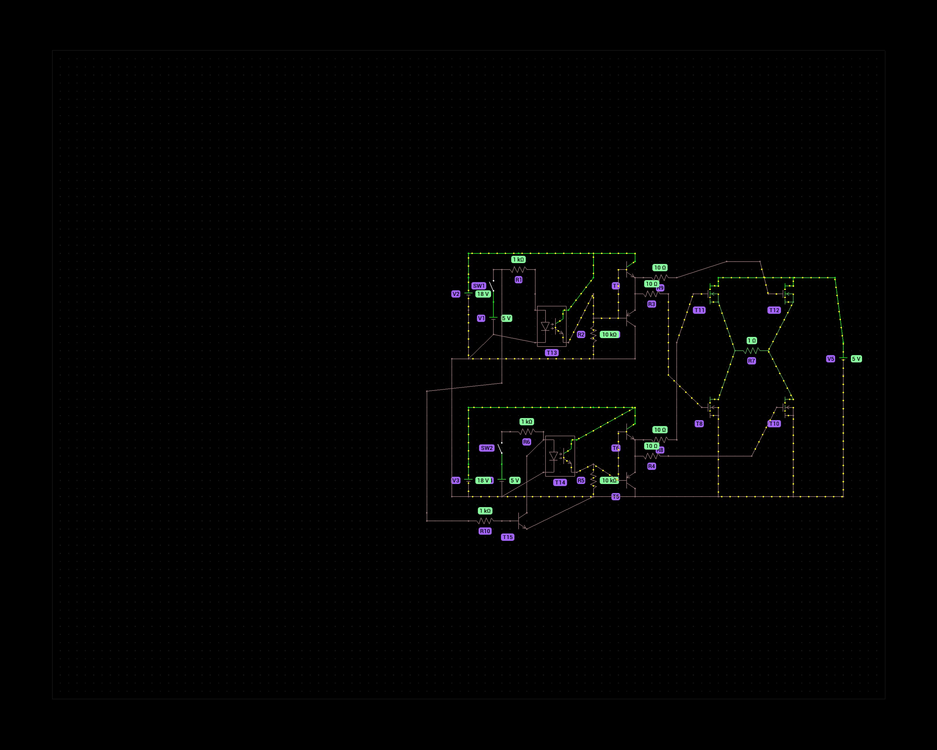
The purpose of this schematic is to control a DC motor that runs at 8V max. That is why I chose 4 N-channel mosfets in the H bridge. P-channels would not fully activate at voltages above -10Vgs but the N-channels can handle 18V at the gate.
The 5v switches represent an Arduino’s digital output pins. One to turn forward, one for reverse. To prevent a failure scenario where both pins are HIGH I added a transistor that prevents current from flowing through the optocoupler on the second half bridge.
Does this circuit make sense? I’m not an electronics engineer, just a hobbyist and have doubts about how effective the gate driving circuit is of the mosfets.
Thanks!
I don’t think the PWM on the arduino is slow for your application. Motors are actually great for filtering. Even if the current is not filtered, mechanically it is so slow that you can go as low as 100Hz and still drive the motor acceptably well.