
So the lone LED in the middle, with two resistors, is going to be on all the time, as a night light to the night light.
If the rest of the LEDs are on a switch, will I have to run two completely separate wires for the single LED, isolating it on its own circuit?
I’m tentatively planning on doing that, using heat shrink or something like that to tidy up the wires, then use two DC barrel jacks to connect each set of wires to the board. Are there any potential problems with this plan?
Best way is probably to run power right to the pcb, connect your always on led to positive and ground, the rest of the LEDs to ground then run the positive to one side of the switch and the other side of the switch to the anode of the LEDs that you want the switch to turn on.
If you don’t want the switch connected right to the PCB you could always add wires to extend it
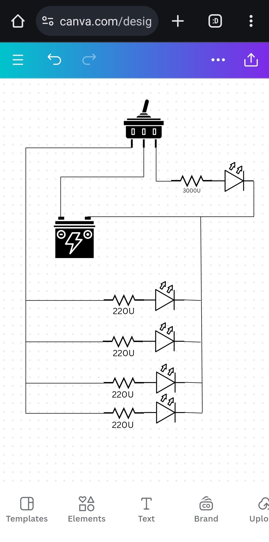
Something like this?
Also, are there any glaring issues with doing it like this?
This circuit does work but the always on LED can just be connected right to positive it doesn’t need to also be connected to the switch. It does depend on which switch type you’re using, I’m assuming it’s spdt like in your diagram which means that with your current circuit when the switch is in one position the main LEDs will be on and the indicator one is off and with it in the other position the indicator one will be on and the main ones off. Which also works fine if that’s your intention.
Shouldn’t see any issues, this is how it’s usually done. The only thing to watch out for is the longer your wires to the switch the more resistance your adding but it should be negligible unless it’s crazy long.
What the other poster said about running three wires up also works, and is essentially the same circuit but It depends how it’s being set up, I assumed it was going in an enclosure of some kind with the switch on the outside of the enclosure. If the switch is going to be in-between and outlet and your LEDs it would make more sense to run 3 wires up instead of running wires back down for the switch.
I’m the middle of reading your comment I realized what I did wrong when making it in the breadboard.
So I got the switch and parallel LEDs working, but the single LED connected directly to positive wouldn’t light. The resistor and LED made a loop back onto the same positive side of the breadboard, so the current had no reason to flow through them.
You really need a circuit diagram for this question to make sense… I think for both of us too. I have no idea what connections you’re making where and what is in serial versus parallel, or where you’re intending to add power. KiCAD is not too hard but, like all CAD there is a learning curve. I can say first hand, KiCAD is far easier than FreeCAD or Blender.
It sounds like you want a circuit like what a self lit double pole switch has built in. With those switches, you have 3 terminals. The #2 middle terminal is your incoming power from the supply. When 1-2 are connected, your main circuit is powered. When 2-3 are powered, the main circuit is cut, but there is a light, (usually a neon lamp and resistor because it is for AC, but it can be a resistor and LED for a DC rated switch). The light can be lit because both the live and neutral are present on the switch. It is only possible to have the internal light if 2 polarities are present to complete the circuit. You can do the same thing externally by wiring a light in the 3rd terminal of a double pole switch. You just route the LED the right way depending on if you’re switching ground or the positive rail.
With LED’s be sure you understand star power and grounding, or you’re going to have some lights that are brighter than others.
Yeah, I’m not surprised help is limited without a diagram. Maybe I can get around to making one tonight
Is this going in a light on the roof or something, and your switch on the wall? Im happy to help out but I think it would help to know what the installation will be and what wires youve got to work with
The lights are going to be on a wall, around 7’ up, with the power running straight down to an outlet. About halfway up will be a switch
Oh right so you arent using existing wiring, and can run any wires you need? (That makes it easy)
Yep, the power source is a 7.5V wall wart
Awesome well what i would do is have the power supply inside the wall (behind the switch) on a plug base, powered 24/7. Id then run: 1 cable up to the light as your negative. 1 cable up to the light as your night light. 1 cable up to the light as your switched positive.
Bonus: If you want the night light to turn off when the main light is on, just run it off the normally closed terminal of the switch instead. Either way - just 3 wires from the bottom to the top, all 7.5vdc.
Any grade of cable is fine since its extra low voltage. Jusy make sure its like 1mm2 or greater so you dont suffer from voltage drop. If you just have one or two of these lights any switch should be fine with that load.
Is that what you were wanting to verify?
