- cross-posted to:
- [email protected]
- cross-posted to:
- [email protected]
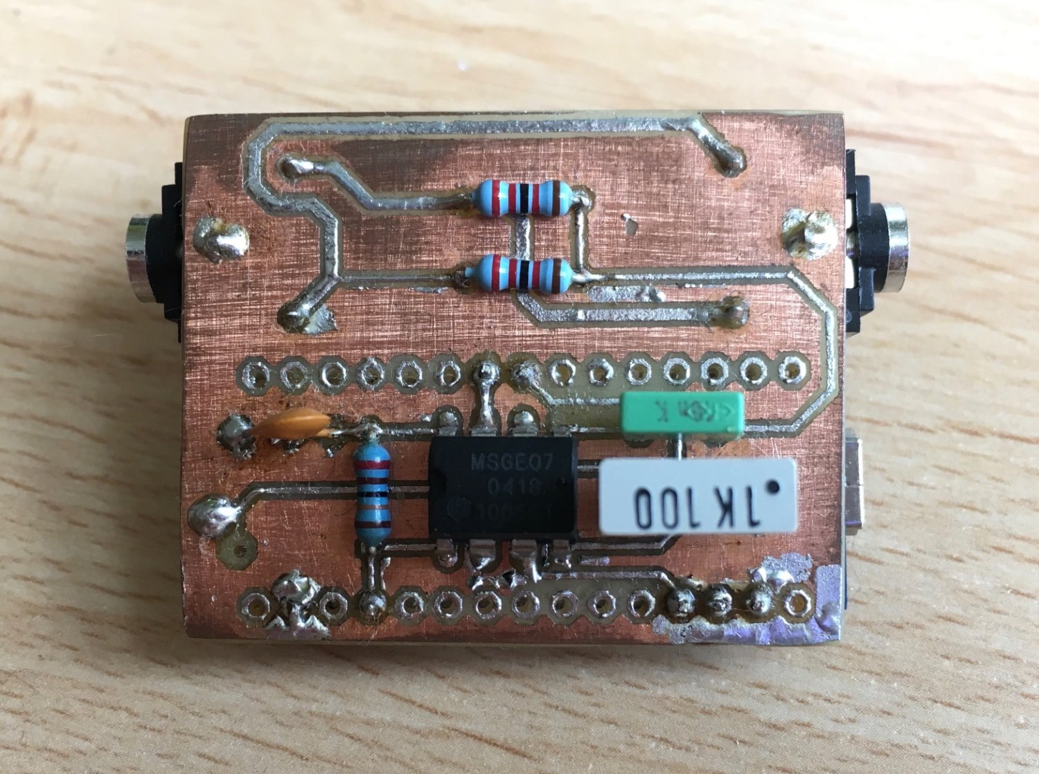
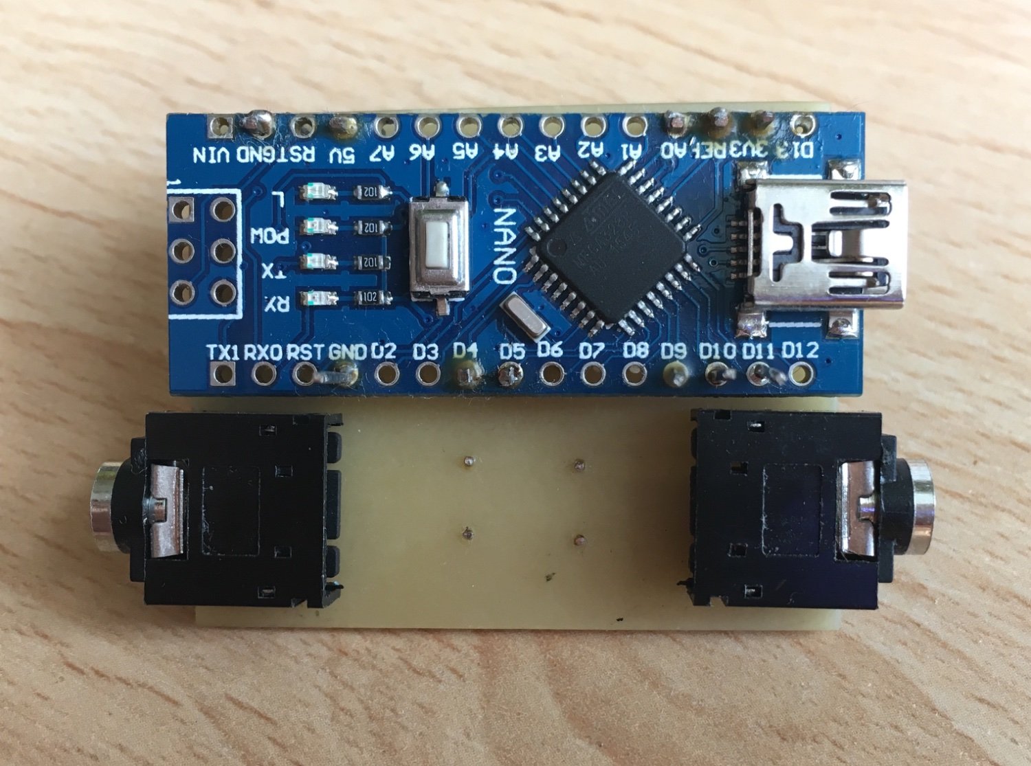
This was my first try developing my own pcb with the toner transfer method. I did this project many years back but it works perfectly to this day.
It filters an audio signal and drives led strips so they pulsate to the beat of a song.
Is this one of those IYKYK or is there further explanation of the process involved?
Sounds amazing and fascinating but I have no idea how it’s accomplished.
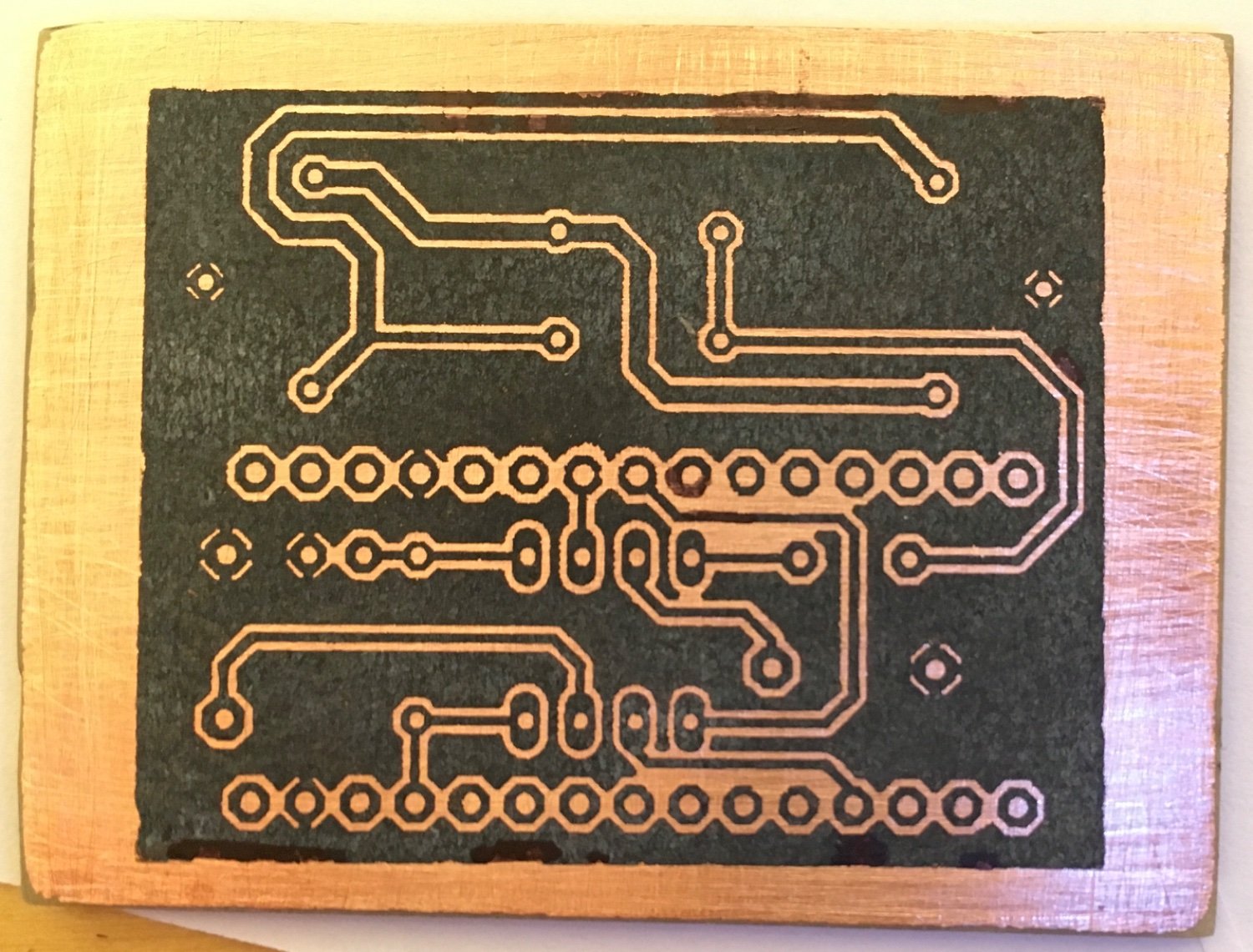
I just printed the design on a glossy paper and used an iron to transfer the toner from the paper onto the pcb (last image). The toner protects the underlying copper in the etching process, so only the free copper gets etched away. I used Na2S2O8 for etching.
I’m assuming you’re not super familiar with PCB fabrication? The toner transfer is a way to get small, repeatable, and precise definition of the component pads and traces - at home - without needing the expensive industrial machinery that fab houses have.
The toner ’print’ is a negative image, placed on a sheet of copper mounted to (usually) fiberglass. Much like masking off areas when painting, the ‘print’ protects the copper surface in select areas you want to keep safe when the whole board goes into the acid bath to dissolve the unprotected copper - leaving copper only where your ‘print’ was, and hopefully no shorts/grounds.
Definitely cool to have the ability to DIY fine pitch if you’re manually mounting SMT components or want higher board density, beats out the hand drawn permanent marker lines I’ve done in the past 😅