
The main idea i had was to individually sleeve these and potentially remove the split part as i don’t like the idea of buying extensions and stuff even more cable inside my case.
On the other hand i would be ok with removing the combined sleeve and 3d print some combs to make the cables look better, especially since the mobo cable has a huge piece of heatshrink making it nearly impossible to look good.
But i have no clue what that little component is and if it only exists for the split that is in the cable.
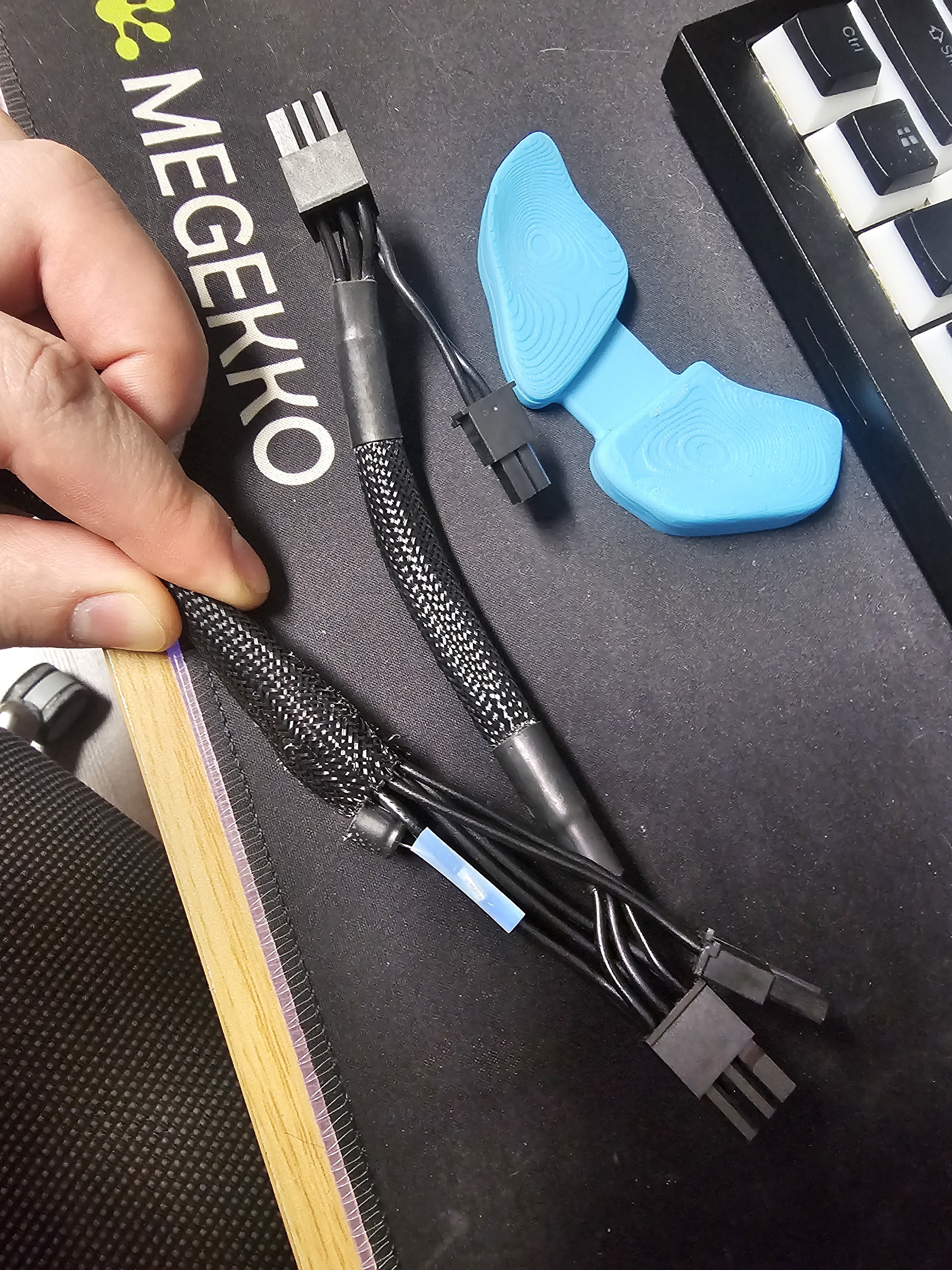
Not sure if this image helps enough…
It was originally hidden in the sleeve under the heatshrink, it might be better to diy some cables instead of messing with these. Having that capacitor visible isn’t going to improve the visuals of my build.
Looks like a capacitor, can we get a pick of the top?
It’s most likely it’s to smooth out voltage from the power supply.
It says: “FP 15Cd 331 16” on it.
My limited knowledge of electronics makes me think that’s some kind of signal filter. I’ve seen similar setups on headphones (usually coupled with a resistor) to filter or reduce certain frequencies.
What exactly it’s doing in your setup, I can’t say.
It’s either a signal filter or more likely a power stabilizer to handle fast load spikes when the device suddenly changes power usage levels.
I’ve learned the hard way that every ttl chip gets it’s own cap between vcc and ground.
Yeah, that’s about 95% a filter cap. Hoghly likely you don’t need one if you’re gonna make your own cables, with short runs.