
More pics: https://imgur.com/a/iYK45eQ
I’ve been lurking r/emk for a while and never shared anything useful, but since Lemmy community is getting traction, I thought it’s a good opportunity to brag a little.
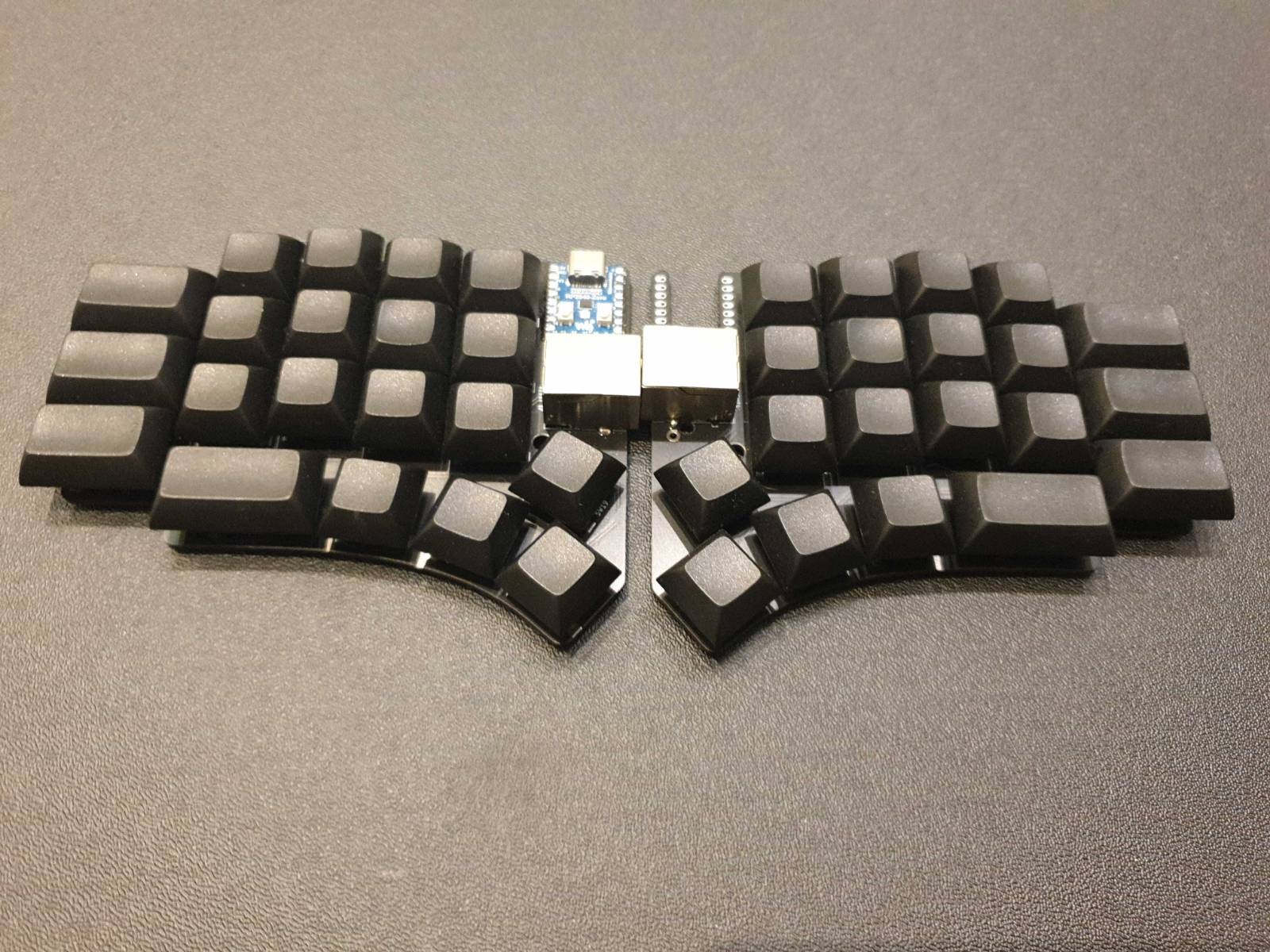
I just got the first prototype of my custom ergo board working a few days ago. It still has no plate, no name, no case and a few things I’d like to tweak eventually, but I’m very happy about my first PCB design and first time I used KiCAD not turning into a piece of junk immediately.
I’ve been looking at a lot of thumb cluster designs and asking some people using all the kyrias, hillsides, irises and such how usable/comfortable the upper keys are and decided to try out something like Pinky4/RockOn/pinkies out in hope of having a comfortable 4 key thumb cluster on a flat keyboard. I’m still getting used to it and slowly developing muscle memory, but I think it’s a moderate success. I use the upper keys as layer toggle and it’s not bad if a little unfamiliar. I’ve also considered going splayed for a moment, but decided to go with 1.5u pinky column, so I can place my pinky anywhere I like and it’s an absolute joy. I love the look and feel. Sourcing keycaps is definitely a little awkward, but I only use blank DSA anyway. Having some troubles with setting up my first handwired split I never got around to finish, then my Let’s Split PCB from falbatech, which I never got to finish (see the pattern?) I decided to go with single MCU design and was unsure about the connector until I saw cheapino by tompi and I knew that was it. Very sturdy and solid connection. However the standard cat5 cable is a little too stiff for my liking and I’m gonna look for something more flexible. I’m happy to see my first PCB design work, however, it’s not without its flaws. I copied the design from cheapino, but didn’t notice that some pins on the RJ45 are messed up and I had to make a custom cable, or one row pin would be permanently shorted to ground. Another issue is that I forgot to measure the footprint for RP2040Zero I got from SadekBaroudi (thank you for awesome repository and your boards being a huge inspiration) so it can’t be mounted from underneath the PCB as I originally planned. This will make designing the plate a little more difficult.
That being said, I’m really happy with what I achieved. The board is comfy, PCBs from JLCPCB are great quality and programming RP2040 is much less tedious and forgiving than pro micro, with the added benefit of a USB socket that doesn’t break away the minute you look at it with too much force. It has support for both hot-swap and soldered low profile Gateron KS-27 switches, that are cheap and pretty cool in my opinion and the spacing is a little tighter at 18.5mm making the board pretty portable. (Aside from the switches falling out of the sockets due to lack of the plate I still haven’t got enough time to cut out) I also broke my fear of PCB design and the whole “I’m too dumb for this.”
I’m nowhere near finished with this one, however I don’t know how long it will take me to make the plate, case and another revision of PCB, since I already started using it as a daily driver and I love it. Once I finish everything I planned, I will open source the PCB, CAD and QMK files. Hope you enjoy it.
Cheers, Arth.
PS: I’m so glad we’ve moved into a decentralised network, no matter how good or bad Lemmy is. I only joined today, but for most of the problems with today’s internet, FOSS is the answer. Great move!
May I ask how did you get over the vbus issue, I have a split that uses the zero too.
I’m not sure what vbus issue you are talking about. The whole point of this design is to have a board that essentially works like a monoblock, or just a regular keyboard. As you can see on the picture, the right half doesn’t have an MCU(RP2040Zero) and the cable doesn’t transmit I²C/Serial data, but physically connects rows and columns of the keyboard. The only catch is that I had to use Japanese Duplex Matrix to reduce the number of columns, so that I can connect the halves using just 7 wires on the Ethernet cable. That way you can avoid all the technical complexity of dual MCU split boards at the cost of only having room for additional hardware on the left side, because the rest of the pins are unavailable from the right side.
EDIT: that being said, the matrix technically has six columns, so there are four empty positions on each side that can be used for an encoder or additional keys. ;)
Ahh, sorry, I thought you were doing a split keyboard with an mcu on each halve. This Japanese Duplex Matrix has caught my attention now, very interesting keyboard you have there.
Thank you. Although it’s not an entirely original idea. As I mentioned, I decided to implement what tompi did on his cheapino to my design. The schematic is almost identical (copying the same mistakes as well). But yeah, I think it’s very interesting and mostly unexplored in mainstream boards.