

Greetings fellow lemmings! I have a problem and i was hoping your smart brains could help me solve it. I want to use an arduino and some addressable LED strips as an „ambilight“ upgrade for my pc. I soldered everything according to some instructions on the webz. I also provide enough electricity for the strips via a 12v charger. When I power them on (no matter if the arduino is turned on or not), they just blink randomly. Only a few led on the 4 strips I connected (to make corners for my monitor). The data input from pin 5 on my arduino is completely ignored when it is turned on. So I think it’s a wiring problem. But I don’t see the issue. On the picture you see the input connections i soldered. The strips are just connected together by wires. Ground to ground, data to data, power to power. Is my dumb smooth brain keeping me from my plans, or is there something broken? I only have replacement led strips, but I don’t know why the arduino or the power supply should be broken
update for everyone who cares: A friend of mine and me were troubleshooting (he has a multimeter and another arduino), and we came to the conclusion that I need an even stronger power supply. The leds on the new strips are much more powerhungry than the old ones. So I’ll try to get a more reasonable power supply (we did the math and I need one with 5V and 20 Amps, the current one is 12V with 1.4 Amps) and I will post another update.
Thank you so much for your help, everyone!
next update: With a lab power supply we measured, that the strips need much less power than it says in the description of the LED strip. It works flawlessly with a 5v and 4a power supply. My connections were right, but not the power delivery.
Thank you again everybody! I learned quite a lot 😊
It will be very difficult for someone over the internet to help you troubleshoot without some type of schematic of what you’re trying to accomplish.
I know, but I already got pretty good answers here 😊 i thought the connections are so easy that a schematic is not needed, but I’ll provide one lather when I have the time to draw one. Thanks for the advice!
(we did the math and I need one with 5V and 20 Amps, the current one is 12V with 1.4 Amps)
This is a major issue here. Either your LEDs are 5V or they’re 12V but they’re never both and injecting 12V into a 5V strip is going to burn the strip out.
I assume you’re powering the arduino separately and if so, you’ll need to tie the ground from the arduino to the ground of the strip so that they match.
What strip do you have exactly and how many LEDs are you going to run?
Listen to this guy. Most LED tape is 12V or 24V. A 5V 20A power supply may meet your wattage requirement, but the LED tape will need it at 12V to function properly.
Have you verified that the power supply wiring is correct? Red = + Black = -. I have had supplies where the red and black were reversed during manufacture, I have also had led strips where the labeling was reversed.
That might account for the behavior.
Is the arduino getting power in this situation? It looks like it is only connected to data and ground. I have no experience with arduinos, but I would think you would have 3 wires connecting to it. +, -, and data.
You say 12v for the lights, but input on the strips says +5v
Thank you for your answer!
Have you verified that the power supply wiring is correct? Red = + Black = -. I have had supplies where the red and black were reversed during manufacture, I have also had led strips where the labeling was reversed.
I have not, that’s a good point! I‘ll see if I can find a way to Check that.
Is the arduino getting power in this situation? It looks like it is only connected to data and ground. I have no experience with arduinos, but I would think you would have 3 wires connecting to it. +, -, and data.
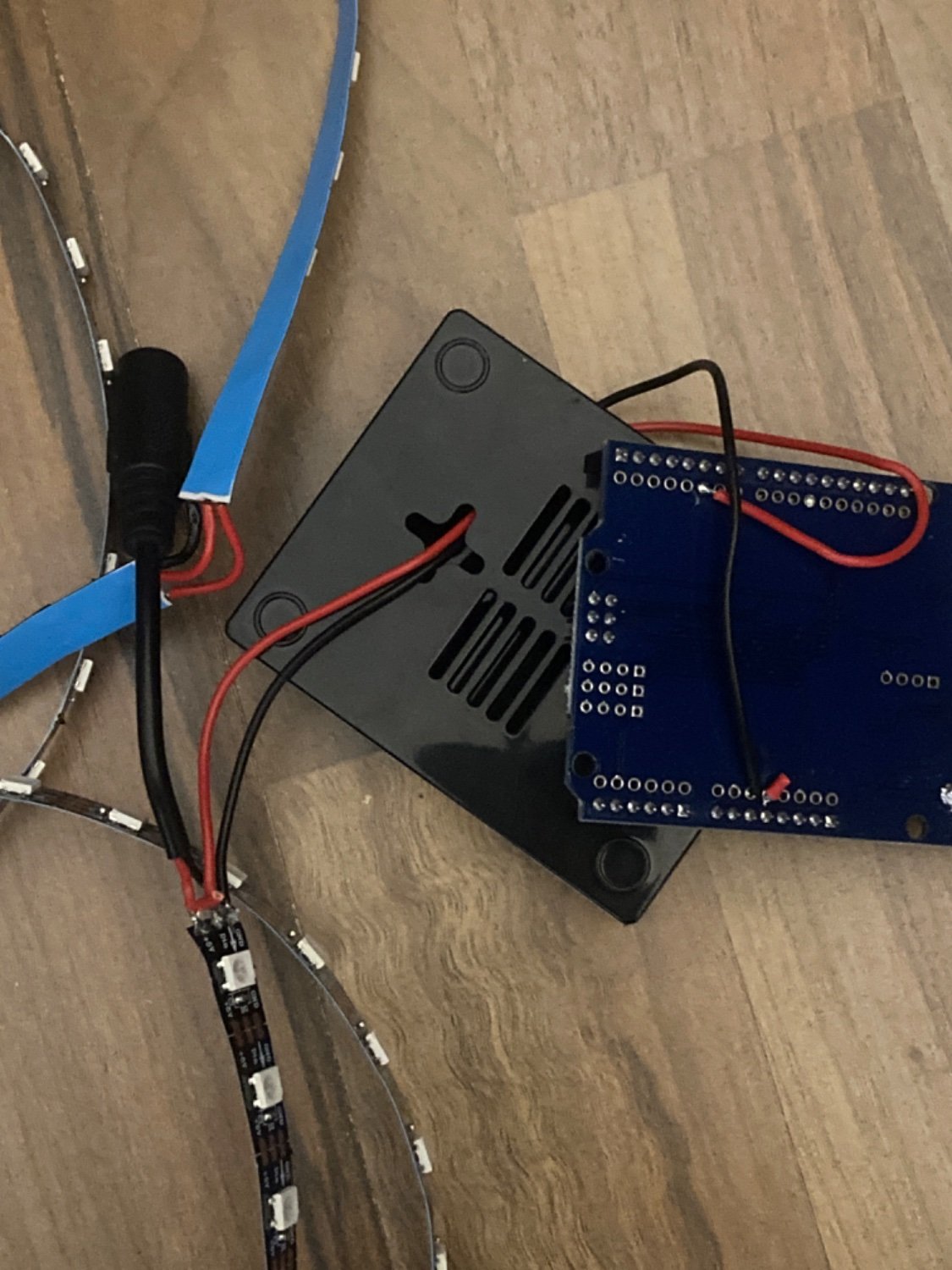
I disconnected the cables when making the picture, so you can see the wiring I soldered. I connected +5v with the red wire of the power supply, data with pad5 on my arduino and ground to the black wire of the supply and ground on the arduino.
You say 12v for the lights, but input on the strips says +5v
The supply was already in work as an ambulatory supply before, i just got new LED strips with even more LEDs (got a new, bigger screen). In the online Tutorials they also use 12v supplies. Unfortunately I have no weaker ones to try out
Unfortunately your photo is a bit meaningless.
Tell us exactly how you have connected all these things, including the power supply to the Arduino and power supply to the LED strips.
And always, always test each of the parts before soldering it all together. It may sound pathetic, but it is going to save you lots of angry hours when searching for errors in the final system.
Adafruit and Sparkfun have decent tutorials on how to connect, power, and control these types of strips.
Here’s one: https://learn.adafruit.com/rgb-led-strips/overview
need one with 5V and 20 Amps, the current one is 12V with 1.4 Amps) and I will post another update.
Call your friend again when you have the new power supply.
20A is a lot for these tiny spaghetti wires, and it is also way too much for one LED strip. But if you divide the 20A properly, it may work.
Is your light strip the exact one used in the guide you followed?
Because when I’ve done leds with esp32, leds of the same model can require different code libraries or #includes based on who manufactured the particular led.
For example I had an 8*16 led array that was blinking randomly when I first started until I realized it was scrolling text sideways and mirrored because there were 3 different types of the same led array.
I soldered everything according to some instructions on the webz.
Did you test your equipment before soldering it together? Then after soldering it does not work?
I also provide enough electricity for the strips via a 12v charger. When I power them on (no matter if the arduino is turned on or not), they just blink randomly. Only a few led on the 4 strips I connected (to make corners for my monitor).
Is it three wires you are connecting: 5V power, +data (PD5), then ground connection on the strip?
The data input from pin 5 on my arduino is completely ignored when it is turned on. So I think it’s a wiring problem. But I don’t see the issue.
By this you mean that no V is seen or it is acting like it is not connected, it is binary so it has the neccasary V or it does not (0V or 5V).
On the picture you see the input connections i soldered. The strips are just connected together by wires. Ground to ground, data to data, power to power.
…is there something broken? I only have replacement led strips, but I don’t know why the arduino or the power supply should be broken
You need to make sure you did not fry the arduino.
Quick search I found this short video with great information:
- Beginner’s Guide to Using LED Strips with Arduino [08:58 | MAY 18 2020 | MakeUseOf] https://youtu.be/5M24QUVE0iU
Here is the article if you want to read instead or watch and read:
Thank you for your quick response!
Did you test your equipment before soldering it together? Then after soldering it does not work?
Unfortunately I did not, but the arduino and the power supply were already in use as an ambilight some months ago (I bought a preassembled kit back then). I got a new screen, so i stored the devices until yesterday, when my new LED strips arrived. Everything worked until then.
Is it three wires you are connecting: 5V power, +data (PD5), then ground connection on the strip?
Exactly. Also for good measure I also connected ground from the arduino with the ground pin from the strip. Is that a problem? It used to be wired that way before… but the old strips had less LEDs.
By this you mean that no V is seen or it is acting like it is not connected, it is binary so it has the neccasary V or it does not (0V or 5V).
I updated the fastled library on the arduino und set it to use port5 of the arduino. When everything is connected I turn on prismatik and it says it sends signals to the arduino. The work indicating led on the arduino blinks accordingly. But the led strip blink does not change. Unfortunately I have no device to measure if there is any output from the pad.
You need to make sure you did not fry the arduino. Is there a way to check it by software? But it behaves as it used to, when the old ambilight was working.
Quick search I found this short video with great information:
Thank you for the recommendations! I‘ll check them out!
Is there a way to check it by software? But it behaves as it used to, when the old ambilight was working.
It would be dead (no lights or anything) if you fried it; I have fried a good amount on my end when I was doing projects with them, hahaha.
I’ll be on hold until you get the chance to watch and read the video and article; it should be able to help you figure out if you are missing some of the basics.
I just posted the update as an edit of this post.
Thank you again for the help and the links, that was really helpful while troubleshooting!
