
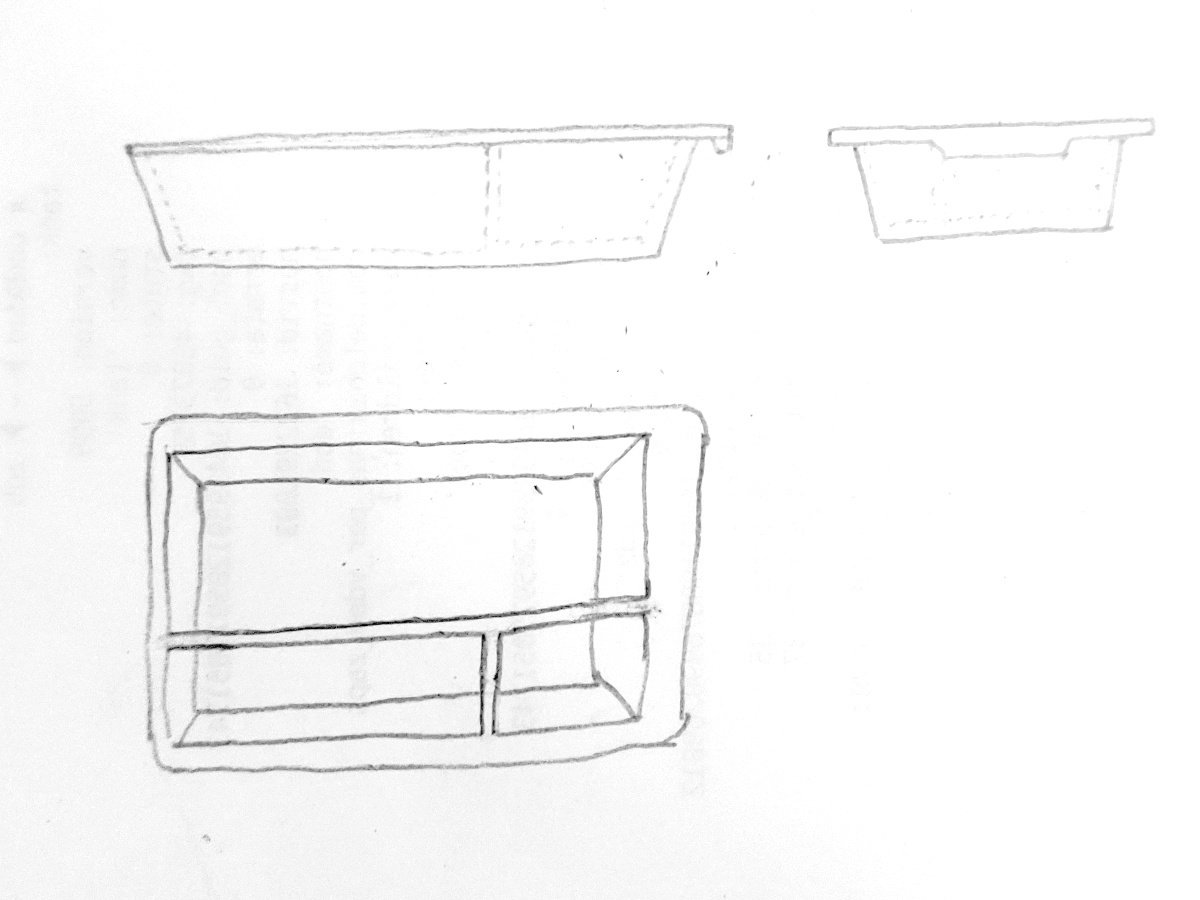
I’m new to freecad, so far I made it this way :
Sketch a rectangle for the top surface, pad it, add filets for the corners. Then select to bottom face, make a new sketch, another rectangle, then a datum plane 40mm below, sketch another smaller rectangle, and make a loft between the two to create the bottom of the tray.
Now for the hole I made a rectangle on the top face and made a pocket with an angle.
Downside of this, the thickness of the walls is not equal. Ideally I’d like a 1.5mm thickness everywhere. And I’m not really sure how to proceed to make the separators inside the tray.
What is the most efficient way to do it? thanks
What will the manufacturing method be ?
3D printing, I plan on placing the left angled side (of the top left sketch) on the printing bed, this way I should avoid supports.
Use the Part Design workbench (you probably are already, but no one’s said it yet). Sketch a rectangle for the top of the whole tray, not the surface. Pad it down 40mm. Add a draft to set the angle of the sides. Use the thickness tool to dig out the middle of the top face - to a thickness of your exact choosing, which will be consistent everywhere. Now you have a trapezoidal bin.
Then how do you make the separators. Um, draw a sketch with the tee on the inside bottom and pad it… and then the separators don’t reach the angled side walls. Oo, how about this: on the inside bottom, draw a sketch of the small square of material at the junction of the tee, and pad this tiny pillar up to the top of the tray. Then start a sketch on a side wall, External Geometry the near sides of the pillar in, and they’ll be projected onto the angled side wall. Then loft the two rectangles together. Yeah? Yeah? No. That didn’t work. The projection was normal to the angled wall, not to the side of the pillar.
HAHAHA ok. Select a side of the pillar. Pad it, select Up to Face, and pick the angled inside . Presto!
Then stick the lip on top and the grippy bit and that.
I hope this was helpful and entertaining.
Note that attaching subsequent operations to generated geometry like this (faces made by pads, etc.) will make the model extremely fragile and making basically any change upstream from that will break it every time.
This may or may not improve with the upcoming 1.0 release where the topological naming bug is “fixed,” but I’m not counting on it until I see it for myself.
FYI for anyone else stumbling on this in the future, you cannot at present pad-to-face in more than one direction at a time, i.e. the “symmetrical” option you can use with a normal pad is not present. Also, you can’t pad-to-face onto any surface that is not geometrically flat; curved surfaces or even intersecting with two faces with an angle in between them will not work.
Thanks for these tips and provisos - they are true and important. … How would you do the divider?
In this case as a loft. Not say that’s necessarily the right way to do it, but that’s how I’d do it. See my other comment on the matter here.
thanks, I’ll try that. so far I only used the Part Design and Sketecher workbenches, I’ll try the Draft.
To be clear, I’m pretty sure that poster was referring to the Draft tool in the PartDesign workbench:

…And not the Draft workbench, if that’s where you were going.
Oh! Oh yeah, that’s what I meant, sorry
I never gave the Draft workbench any thought at all, until watching Mango Jelly Solutions’ FreeCAD tutorial videos, which I heartily recommend. Heck, sometimes I can’t get something modelled properly and just starting the video about it somehow reminds me of the right mindset :) https://www.youtube.com/c/MangoJellySolutions https://ko-fi.com/mang0
I would make the tapered main bucket out of a loft made of two sketches that describe the dimensions of the upper and lower extremities of the shape. This can be hollow; there is no need to put a hole through it with a pocket. The hole and outer walls can be part of your sketch.
Similarly do not fillet the corners with PartDesign fillets. I mean, you can if you really want to but you can just use Sketch fillets inside your sketches and then FreeCAD won’t incessantly break your fillets (and thus the model) any time you change anything…
Example:


If everything needs to be tapered, honestly I would use lofts for all of the vertical components. Make liberal use of the “carbon copy” sketcher feature to make construction lines out of your two master sketches, and then all the other sketches you make for the dividers, perimeter lip, etc. can automatically tie themselves to any dimension adjustments you make to the bin itself.

Example .FCStd file: here.
Edit: It occurs to me that you could also make the tapered tray body by making a solid loft with no hole in it and then using the Thickness tool on the resulting It solid. This would be mechanically simpler, but would result in not having sketch geometry of either the inner or outer wall (depending on which side you tell the thickness to be on) which might hamper future additions/modifications.
Is there no shell option in freecad? That would take care of the inconsistent thickness. Otherwise it sounds like a decent workflow
Believe it’s the Part Thickness Tool
deleted by creator

