Here’s a close up picture of the print itself: https://imgur.com/a/flJjhGs. It’s printed in PETG with 40% infill. I printed it first in PLA, but then it snapped immediately (thankfully not on my face). The only reason why I didn’t use PETG from the get go was that I actually didn’t know you could print it without an enclosure.
One thing that I don’t like about this setup is that I’m missing a degree of freedom. If I tilt the monitor upwards, it will also tilt a little bit to the right. It’s good enough for now because I want it to face pretty much straight down anyways, but I would love suggestions and advice! I was thinking about maybe copying this ball and joint I saw on r/functionalprints, but I can’t find that link right now (for obvious reasons).
The monitor is this small lightweight portable monitor (comparable weight to a tablet) (https://a.co/d/0qGzPyC). The boom mic stand is a “heavy duty” mic stand (https://a.co/d/7Cjg8fs).
It is tough building stuff like mounting arms to hold weight without deforming. Most of the time it is best to make joints that only need 1 dof each. Like this is why you see the parallel mechanisms used for articulated desk lamps; each joint only has 1 dof but a bunch are combined. You’ll see something similar with computer monitor arms.

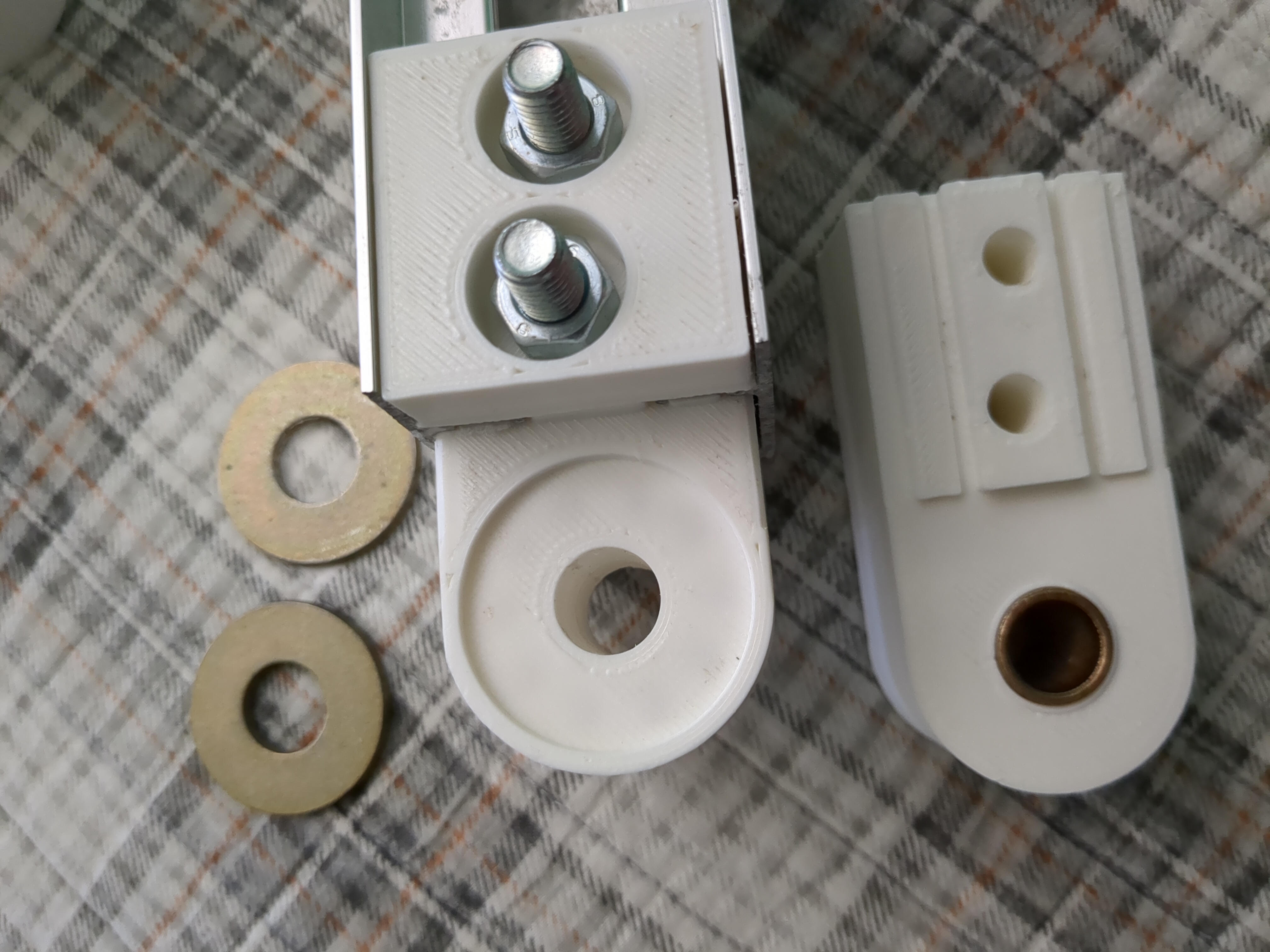
Like this joint has a recess in the top and bottom for washers with a bolt passing through the middle. It may seem like the bolt through the middle would be what holds the load and any slop in the joint, but this is not the case. The bolt is only holding the compression of the assembly and it is the gap between the washers that controls the slop and weight. It took me a few iterations to imitate this type of joint with a print.

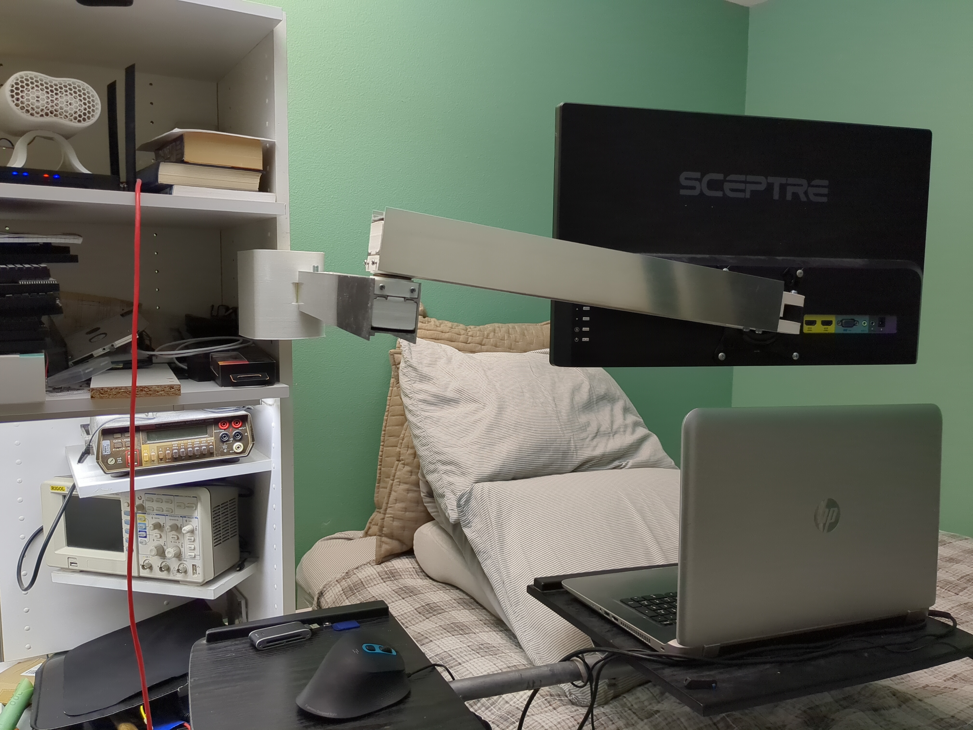
Ultimately, that arm needs another iteration to make it even more rigid, but it is usable like this. That arm is almost 5ft long with a 24in monitor on it.
The way the monitor is hanging is giving me anxiety lol
It is a combo of factors in the design causing the droop, and this is the worst it gets due to leverage. The elbow should be external. This current design can’t compress the joint hard enough to remove the slop. The rails are just the track rail from a glass shower door and are not made to prevent twisting forces. I reinforced the inside with some scrap box tubing. The next iteration will double the first arm span with the extension span in the middle.
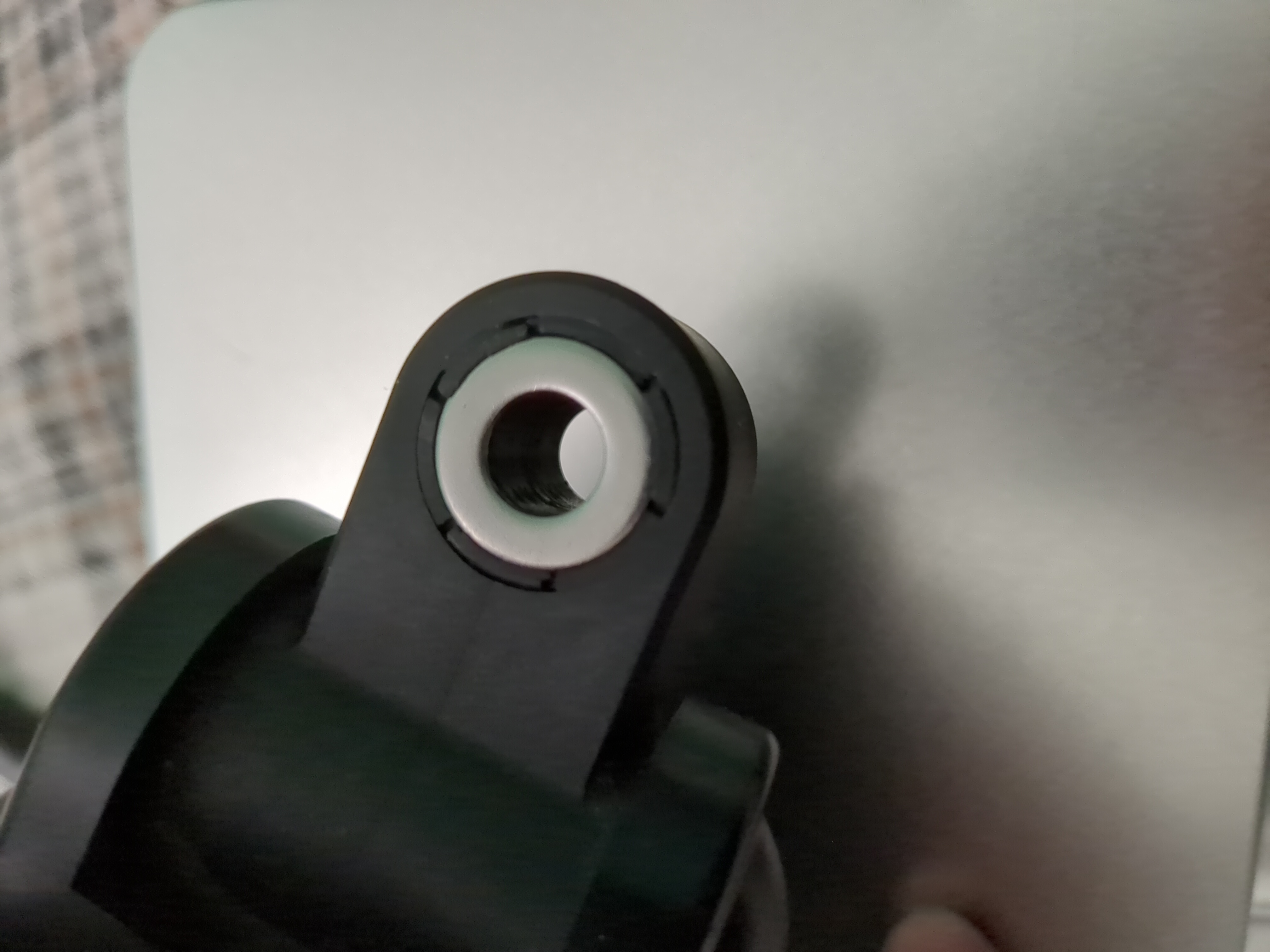
As is, this can still handle pulling tugging and impacts without issue. It is printed in ABS and I did a bunch of experimentation with creating structural voids inside the part that tie everything together. This has very little slicer generated infill throughout each part. I started with a curiosity related to the monitor hinge pictured above. The reason it has the cylindrical vertical holes turned out to be for structural stiffness. If you look very carefully at my one pic of the printed hinge, you’ll barely make out the shadow of similar cylindrical void structures under the infill where the washer goes. This made a much bigger difference than I expected when compared to other iterations (not pictured). This is why there is very little deflection seen in the mounted version at the first joint. The issue is due to torsional load and the elbow design. After this realization, I placed a bunch of voids throughout the base and first joint that tie together all the walls and structure intentionally by design. It makes a big difference. Overall it is a project where good enough will do for now. I only really use the monitor a few times a year when I need to make electronics schematics and circuit boards or am programming embedded hardware.
Anyways, the pics were taken originally to describe the integrated voids design and how it impacted the structural issues I just described more than sharing it like a completed project. It is definitely not one I am proud of as a completed design. I don’t really care about showing off, I’d rather talk about practical engineering. I mostly just need to wait on the budget for the materials to do the next iteration of this one. I’m making the most of having to lay down most of my day due to a broken neck and back that made holding posture for longer than an hour nearly impossible. Almost everything in that pic was curbside junk or donated. At least I’m not paralyzed though. It could always be worse. Sorry for over sharing, but these are my excuses for the (justified) complaint.
I think it’s awesome, great job. If it can handle tugging and all then nothing to worry about i guess haha
That’s pretty cool! I had no idea about those structural voids