- cross-posted to:
- [email protected]
- cross-posted to:
- [email protected]
cross-posted from: https://lemmy.world/post/1287820
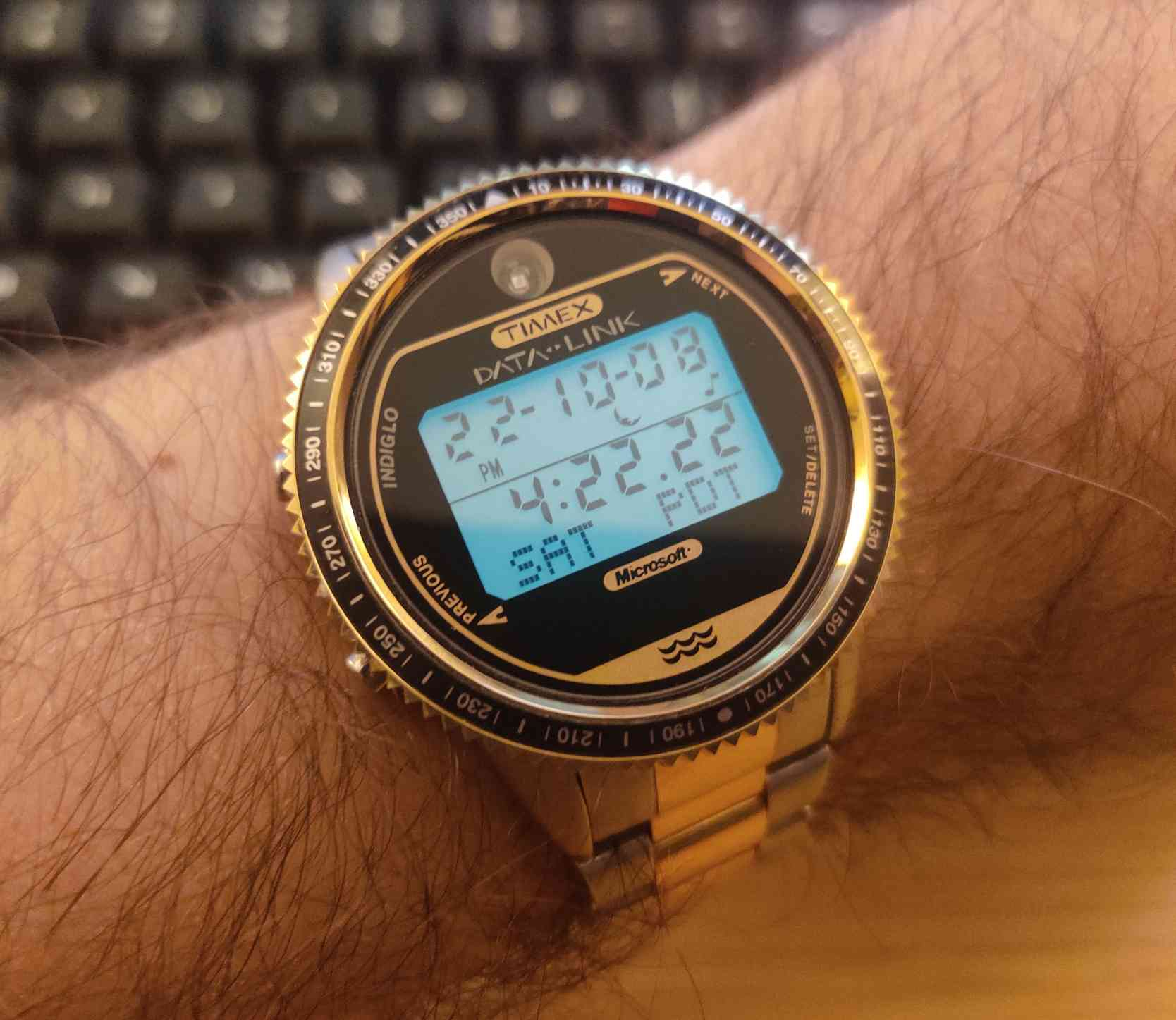
Heya! I thought I’d mention that I’ve been doing a bunch of development on the optical Timex Datalink watches! I have been carefully sniffing data from the original Timex software with a logic analyzer, and have fully reverse engineered every Datalink protocol, the serial Notebook Adapter, and even the CRT syncing graphics! This means that every Datalink device, including every Timex and Motorola watch, all PDAs, and the funny e-BRAIN talking toy is supported!
For those that aren’t familiar, the Timex Datalink is a watch that was introduced in 1994 that is essentially a small PDA on your wrist. The early models (supported by this software) have an optical sensor on the top of the face that receives data via visible light.
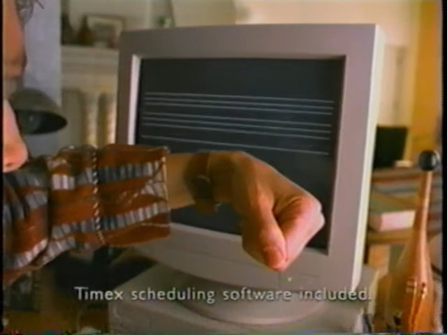
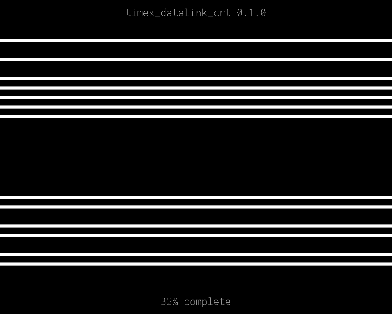
The original data transfer method involves drawing patterns of lines on a CRT monitor for the watch to receive with the optical sensor. CRTs use electron beams that draw scan lines one-by-one from top to bottom, then it returns to the top and repeats for the next frame. This means that the electron guns turn on when its drawing a white line, and and turn off when its drawing the black background. This produces flashing light as the graphics are drawn, which is ultimately received by the optical sensor and decoded by the Timex Datalink device.
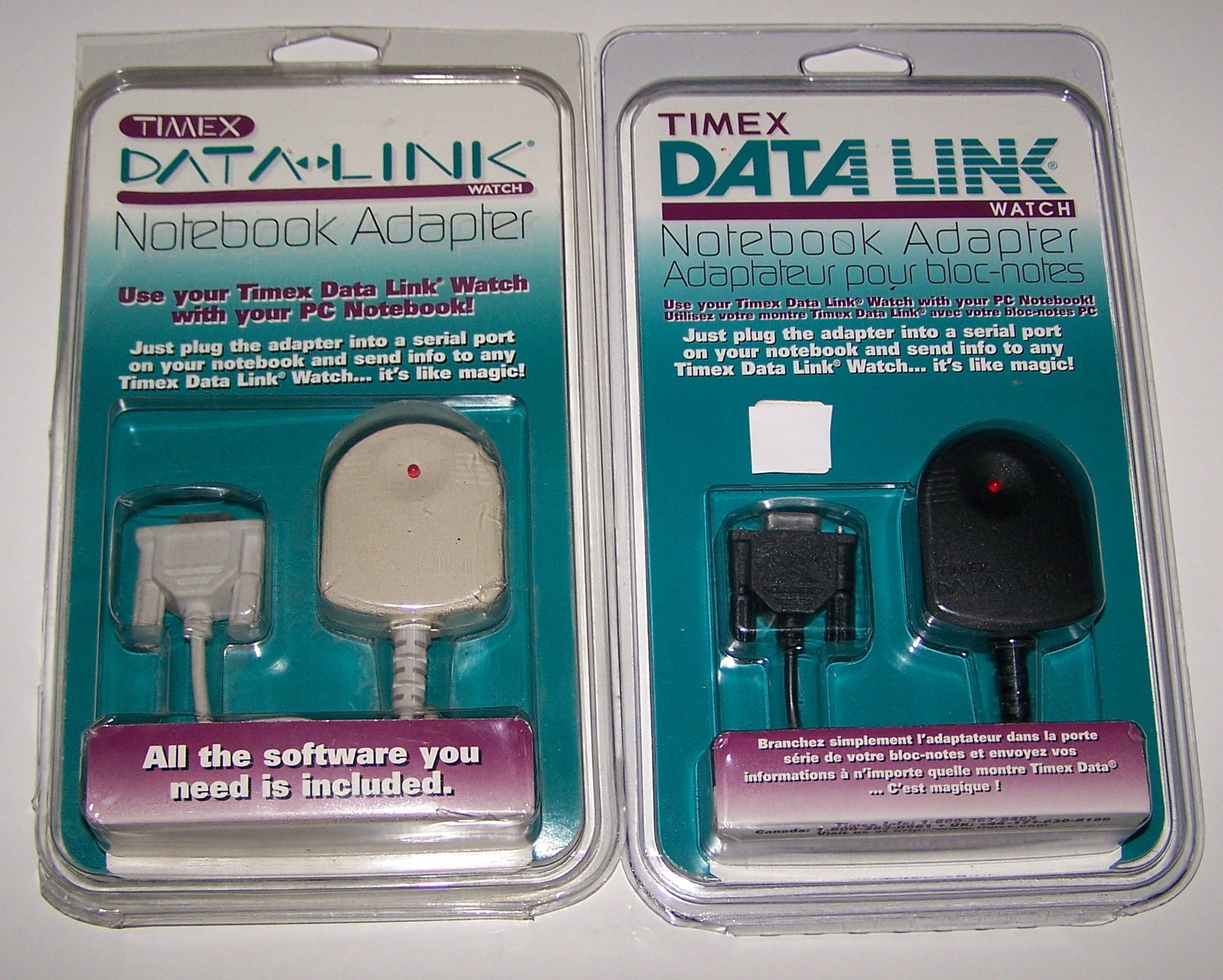
For laptop users, Timex also offered the Datalink Notebook Adapter. Instead of using a CRT monitor, the Notebook Adapter simply flashed a single LED light. This adapter is fully supported by the Timex Datalink software, and sends the same data as a CRT.
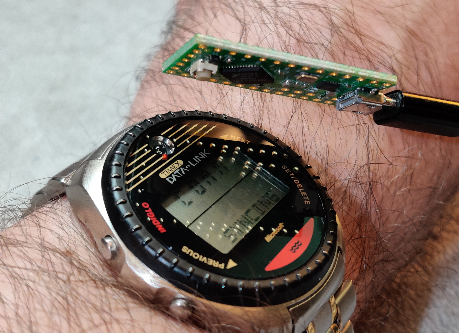
However, Notebook Adapters are rare and expensive now, so I reverse-engineered one! Here’s my timex_datalink_client Ruby library communicating with my DIY Datalink Notebook Adapter to emit data to a Timex Datalink watch!
And if you want to try the reverse-engineered CRT graphics, I got you covered! I reverse-engineered that, too!
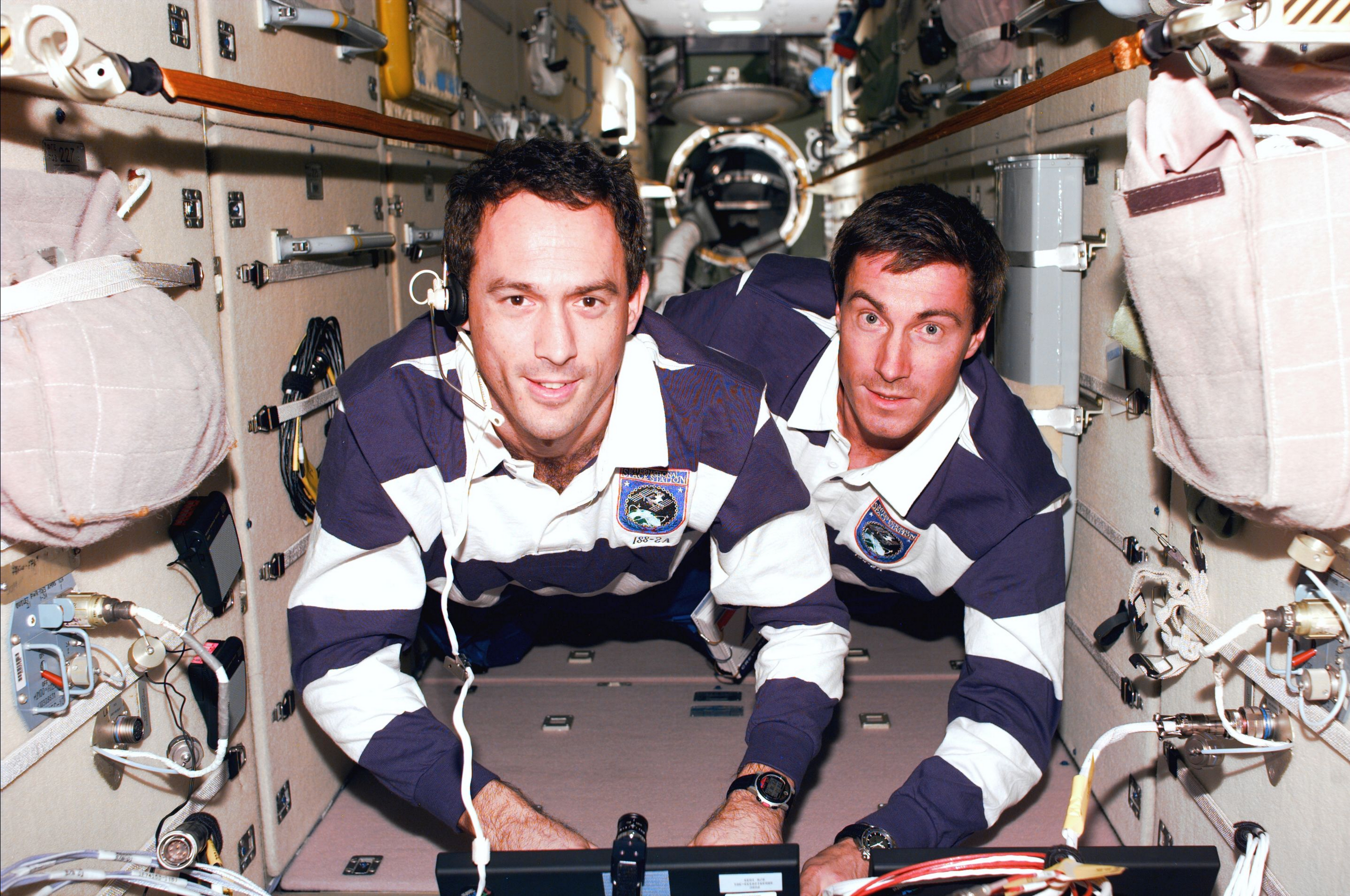
As a fun tidbit, these watches are flight certified by NASA and is one of four watches qualified by NASA for space travel! Here’s a shot of James H. Newman wearing a Datalink watch on the Space Shuttle for STS-88!
Here is my Ruby library with all options for all watches reverse-engineered into a tidy model-based syntax!
Here is a Notebook Adapter emulator that is fully compatible with all Timex software on old and new machines, and also works with my library too!
And if you have an anchor that happens to contain an electron beam and wanna try it, here’s my library for drawing graphics to a CRT to transfer data!
This has all been done over months of careful effort with lots of VMs, Pentium machines, Windows 98SE, logic analyzers, and solving data puzzles little by little. On July 4th, 2023, I’m proud to announce that I have reverse-engineered every Datalink device with 100% feature compatibility! This is definitely a passion project by all means, and I thought I’d pop in and share this passion with y’all!
Enjoy!


Hi! I am the author of this project 👋
I have tried this, but the optical sensor doesn’t seem to pick up on the luminance differences from the LCD panel. It seems like it should work in theory with a panel with enough contrast, but it hasn’t worked on every panel I’ve tried. The sensors are just very sensitive to light bleed though black LCD pixels.
It could possibly work with OLED, and I do have an OLED TV, but I simply haven’t tried it. I haven’t attempted it because I feel that it is even less practical than a USB adapter. Most displays on computers these days are LCDs.
I have thought about possibly using other LEDs to send data, like numlock LEDs on keyboards or software-backed disk activity LEDs. However, the LED not only needs to update fast enough, but it also needs to be very accurate about when to turn the LED on and off. When a few ms off the mark can cause a transfer to fail.
I’ve also thought about esoteric adapters, like the light source being a candle in front of a shutter wheel. A second, slower, mechanical shutter could be moved with an electromagnet between shutter frames. The timing would be challenging, but as long as the timing lines up, it should work! Perhaps a cnc-cut wheel on a stepper motor could do it?
More practically, I thought about a simple adapter that illuminates an LED from sound. Two channel stereo audio that is out of phase might be enough current and voltage to drive an LED. Additionally, a lot of mic connections on TRRS headphone/microphone connectors actually feed a good amount of voltage to the mic, so this could possibly be switched by the presence of audio.
Very cool! I have esp32 laying around in the drawer, so in theory I could use that as long as it can toggle some LEDs fast enough? The next problem is obtaining the Timex, can’t seem to find any in my country.
In case you get your hands on a Datalink, I made a little Discord server with a bunch of archived WristApps, sound themes, and software if you wanna join and pick through it :)
https://discord.gg/nqKcKz2ZbE
That sounds perfect. Depending on the board, it may already have LEDs already present that you can use. It doesn’t take much for the watch to receive data successfully!
You’ll need to add board support in Arduino for your ESP32, and you might need to change the GPIO LED to another pin (which might be an onboard LED, too). Other than that, it should work peachy!
Good luck finding a Datalink watch! There always seems to be something on eBay 🙃 If you find something outside the country, and the seller hasn’t listed it for international shipping, reach out and ask! I’ve done this many times before and most people are happy to ship internationally 👌
A call phone might be the answer. Many phones use OLED screens, meaning an app that sends your calendar to the watch with no extra hardware might be possible.
It might be possible, but that LED on a Notebook Adapter is really going crazy during a transfer. Consider that the original transfer was on a CRT monitor running 640 x 480 @ 60 Hz. The timing is really tight, so I’m going to be measuring in us (microseconds, 1/1,000,000th of a second). This means that…
This is the “electron gun on” time on the picture for a bit of data. Additionally, the CRT is one of the slower ways to transfer data to a watch. With the Notebook Adapter, the data transfer can be increased about 4x the speed without any transfer errors.
A fancy OLED phone can do 120 Hz updates to the screen. This means:
However, since OLED displays don’t have scan lines, this is the fastest this screen can “change states” from “on” to “off.” This also assumes the the entire OLED screen updates simultaneously in a perfect fashion without any artifacts that could cause issues (it probably does). This also assumes that the screen isn’t using PWM for brightness control, and doesn’t flicker (it probably does also).
So in a perfect world where this does work, if we compare possible CRT transfer times to OLED, ~8,333 us / ~35 us leaves us with a transfer speed that is about 240x slower than the CRT solution. This means that transfers that would take 10 seconds on a CRT would take 2,400 seconds, or 40 minutes on an OLED screen in perfect conditions.
There may be some wiggle room with this, like perhaps the “light on” and “light off” timings might be somewhat flexible. But even assuming we can fudge the timing to be off by 4x the calibrated amount, we’d still need 10 minutes to transfer something that would take 10 seconds on a CRT.
Very good info. Guess I hadn’t fully realized it was using scan lines to create infrared-level bandwidth (kilobits) out of a CRT. Very cool stuff.
Agreed! It’s fascinating 😁