

Look at the following image and take a second to think about how you would create a 2D sketch of this shape in CAD with the goal of recreating the profile in a 3d printed part like my end cap.
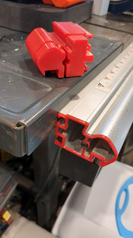
It is unlikely anyone will be able to directly measure all of those curves and angles and make a perfect replica from scratch on the first try. This usually requires a good bit of experience to learn, but the very first thing to do when making this part is to figure out where the critical reference surfaces are in the design. Ask yourself, which features would have had the tightest tolerances by the person that designed this? Which surfaces have loose or undefined tolerances? Which surfaces have well constrained tolerances and are accessible to measure? Go look at the picture again. Really think about this.
Now that you’re back I’m writing a random sentence to move the answer out of your immediate peripheral vision. In my mind, the tee tracks stand out as an excellent set of reference surfaces I can directly measure accurately. Why is this so important? This part is going to need a lot of tweaking to dial in a perfect print. The most important first step in CAD is always to place your part origin well. This design is going to get tweaked, but how am I going to be able to change the measurements. If I only need to move one or two features, but moving those features also changes other features that had bad dimensional references, I am just making a mess. After a few changes, I won’t have a clue how most of my design is constrained.
Solving this problem well is a mindset and is what I call thinking in terms of CAD. In this instance, I can measure the tee tracks and the overall ninety degree angle faces of the back and bottom. Assuming the back two tee slots are the same would be a mistake. In this case they are not. One is imperial the other is metric. I can say after measuring, the center of these tracks is the overall vertical center of the rear face. This does not align with the screw hole, but finding the screw hole’s true center is hard. It is much easier to find the center of the vertical wall that supports the screw hole. This wall is also an ideal way to split the design into measurements on the left and right side. I don’t expect the inner cavities to be extremely accurate reference surfaces but I can likely establish a centerline as it relates to the tee tracks. So now I have come up with two lines of symmetry, the back center between the tee tracks and the screw support wall these can be used to set the coordinate plane origin of the design. Every measurement I make and set for all other surfaces will be relative to this origin point. My entire design will be based on this origin, even the tee tracks, back, and bottom walls. I want to keep as few groups of constraints as possible referenced to each other, this way, when I need to make changes to some small issue in a print, one change only alters the area I need to change.
Picking your origin point well is super critical. The more complex your design is the more important the origin becomes, and it becomes another order of magnitude more important when building complex assemblies.
This lesson works both ways. You can tell a lot about the skill of the person that designed something based on these principals of picking a good origin and identifying good reference surfaces. If you open a design or even import a mesh file. You should be able to pick out critical dimensions and constraints that should exist in a good design. If you take measurements of these areas, (knowing the limitations of a tesselated mesh) and the measurements are nowhere near a typical metric or imperial whole value, you know the person that made the part was not very skilled and problems with the print are likely. I never print someone else’s designs unless I check for some basic principals like this first. As I am building up the part in CAD I also take a few broad measurements across non critical areas and make sure my part is very close to these dimensions as a way to verify my work as I go.
Lastly, this thin wall print pictured is called a Unit Test. The term just means you make as small of a print as you can in order to quickly check your dimensions. Get in the habit of printing lots of little unit tests. It will save you a lot of time and mistakes.
In this instance, it may look like I used the screw hole as the origin, but that is not correct. The hole for the screw is oversized so that I can align the correct surfaces, and then use the screw to hold the unit test in place, and measure my deviation.
This design took around half a dozen of these unit tests to dial in the part well enough that the table saw fence can pass over the cap in both directions without any adverse effects.
I write like I am trying to teach my former self, saying what I wish I had known sooner. Hopefully this finds an audience and is helpful for someone. I am only doing this in an attempt to build community and add some unique content with substance while I have some down time to spare.
I think you could get it first try if you add the photo and measure what you can with calipers as well.
Distortion and height dependency. There are special lenses for industry cameras that remove this issue but no phone has them.
Additionally, image compression is a big issue.