Anyone have a recommendation for a benchtop current sense amplifier?
Sure, there are current sense breakout boards and whatnot. But what I’d like is a convenient device that I can use to instrument a circuit and then monitor its current with my oscilloscope or logic analyzer (Saleae with analog input) along with other signals in the circuit.
Ideal features might be:
- Banana jack inputs and outputs
- Selectable range / sensitivity / sense resistor
- Isolated measurement, so I can measure high-side or low-side currents without worrying too much about the common connection on my scope
- Selectable or automatic power source selection, between circuit-powered and externally-powered
I haven’t seen anything like this in a few targeted searches, and just wondering if someone has any suggestions I might have missed.


I’d be very interested! I am considering building my own little box for this too.
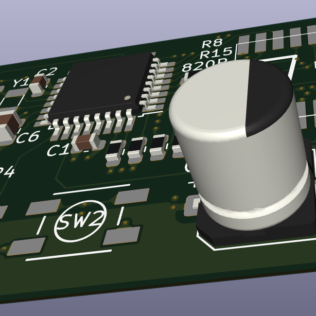
I chose 10kOhm resistors and 10uF X5R MLCC capacitor because they’re already on the board for other reasons. I figured 1.2 Hz corner-frequency was good for my purposes, it probably isn’t good for your purpose but who knows? X5R may have a significant amount of voltage-dependency, but the 0.1Ohm resistor is so small to purposefully minimize the amount of voltage, so that also seems to work out. But yes, a “more serious” anti-aliasing filter may be needed. There’s also a leakage concern due to the very small numbers we’re seeing here, so I’m not entirely confident I got everything correct here.
The AVR64EA32 has a configurable multi-sample. So I can perform 16x samples per ADC hit, returning a 16-bit result. However, the x16 setting of the PGA is 200uV of noise, but this is noise that can be averaged out (and besides, there’s plenty of other noise sources when we’re down to the uV). I’m running at the max-speed of ~300ksample-sec, mostly to average the significant amounts of (theoretical) noise in this circuit.
My sense resistor is 0.1 Ohms. The x16 PGA and 1.024V on-board Vref means that I have a nominal resolution (assuming 12-bits) of 15.625 uV per ADC-step. Well below the noise level, so yeah, significant amounts of oversampling are needed to get any level of trust on those lower-end bits. Assuming I get like 128-oversamples per erm… 0.5ms “required sample rate”, thats ~3 bits of improvement, so I think I’m just barely at like 11 or 12ish bit true resolution (including noise issues). Just napkin math of course.
I’ve got an alternative design almost entirely in the analog domain if you actually want a higher-performance filter. Basically do the same thing except with a different-OpAmp (and there’s current-sense OpAmps at like 50-cents each), and a 4th order Butterworth filter made out of a 2xOpAmp chip and you’d be good.
But this digital design that largely takes advantage of the x16 PGA on the AVR EA is just… you know… so easy in comparison. Its got piss poor performance in the great scheme of things but its good enough for my particular use. Tweaking the anti-aliasing filter and maybe not caring about noise and running at 300kSample/sec might be preferable if you’re needing more bandwidth.
There’s also like 18-bit ADCs that hook up over I2C / SPI. Delta-Sigma ADCs get a lot more bits (though the bits are very noisy… you tend to be able to average the results down to trade bandwidth vs noise in a similar manner to what I did above). Even without the x16 PGA, a 18-bit ADC (or even 24-bit ADCs) will have even more resolution than the design I discussed here.