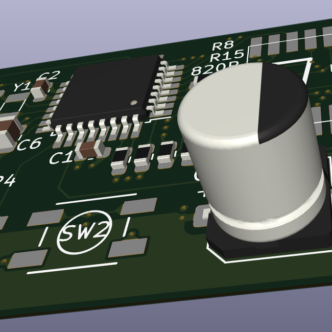
I don’t care what’s it gonna take. I just want a connection. I guess I can connect the VCC to another voltage source, but I have the same thing happened to TX on another circuit board, although that one can “flip” (it is still attached marginally… at one end).
Board: T Deck Lilygo.


Looks like that goes to a via. Could scrape the solder resist back there and bodge straight in rather than try and hook up to the trace.
goes to a “via”? Meaning it’s not directly to the ESP? Is the schematic I provided not what it seems?
well I never said I’d hook it up to the trace, right? Or am I misunderstanding?
So, let me explain. The trace that breaks from the VCC of the P8 IC goes up and to and through a few holes. Those holes lead into the the board to get the needed 3V. You can also go bodge wire from the VCC leg of the P8 direct to the pin 2 of the ESP. You are reading the schematic correctly.
so if I understand correctly, I can either use a pin to solder a bodge wire onto, or solder a bodge wire directly onto the ESP? Hmm then I rather opt for the ESP since this has a larger area to solder onto than the pin.
Yes, bodge wire from the leg of the IC with the busted VCC pad to the 3V leg of the ESP as laid out in the document.