Just working on my recent electronics project and I needed two temperature sensors for it. This time around I didn’t feel like making a full PCB from KiCAD and wanted to keep things simple with a 1/2 size solderable breadboard.
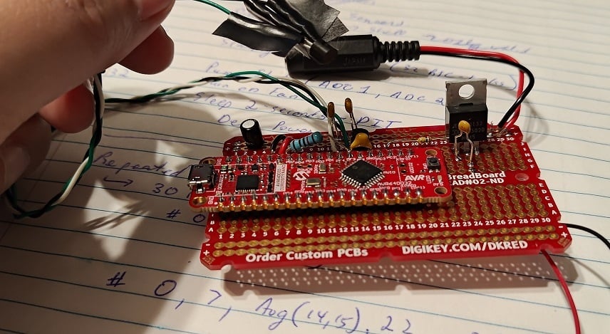
As usual, I’m using an AVR DD (this time: a curiosity nano devboard) for simplicity. (I expect to need the 32768 Hz clock crystal, so a PCB with said clock would be nice. Otherwise, the DIP package is available). The overall circuit is pretty simple, but the topic of discussion today is the MCP970X series temperature sensor.
https://www.microchip.com/en-us/product/mcp9701a
At this point I do recommend people to read the documentation.
The gist is that you simply apply 3.1V to 5.5V between Vdd and Gnd. Vout will have some amount of startup time, and eventually output 400mV + (Temperature-in-C * 19.5mV). For example, my room temperature is ~24C right now and the voltage output is ~920mV.
(There’s clearly errors in my ADC but I’m saving that for later… this device is supposed to be outputting 876mV given the room’s temperature)
With a ~6uA expected current, this device is power-efficient enough to run from most MCU pins. AVR DD’s 50mA-per-pin is overkill, but more importantly, a through-hole design like mine seemingly has substantial inductance on all wires.
The datasheets claim a startup time of 0.8ms. Alas, when I soldered on the MCP9701 and turned on the GPIO-pin, it took over 20ms (!!!) before the oscillating signal finally calmed down and settled upon the room temperature reading.
To counteract this parasitic inductance, I’ve added a 10kOhm resistor and a 10nF capacitor out of my through-hole kit. (E12 resistor kit and E6 capacitor kit). With 220us of startup time now on the GPIO pin and with only 500uA max current going to Vdd… there is no more “ringing” anymore and life is good!
EDIT: I should probably note that my goal was to return to 0.8ms startup time, like the documents suggest. 10kOhm was chosen as 500uA (5V) to 250uA (after charging to 2.5V) is a magnitude more current than I need and is a decent starting point. 10nF was chosen to pair-up with this to give me startup time in the 100us range but not over 800us (I don’t want to be “slowed down” by the charging capacitor, so I want the Vdd charge to be faster than 800us claimed startup time). It should be noted that a 5V over 1000us curve was claimed as a 800us startup in the MCP970x documents if you read all the graphs.
Moving forward, my last task is that of calibration. The on-board ADC of the AVR DD is apparently quite accurate, but the Vref of the microcontroller is +/-4% (!!). With a +/- 2% accuracy of the temperature sensor, there is some calibration I should do.
The ADC errors + Vref errors are expected to just be linear. The temperature-sensor’s error is quadratic however. In both cases, I don’t want to overcomplicate things, so I’m planning on just adding a constant-offset to the mV reading to shift it to the correct spot.
All in all: pretty standard Analog-to-digital conversion issues here. But I figured it’d be a good discussion topic for beginners.
Thanks for your notes on that part. Sometimes, when I didn’t have a special temperature sensor part at hand, I have used a normal silicon diode as a temperature sensor. That works okay, but calibrating it is a little annoying, as it isn’t exactly linear. For more serious projects, I usually use the DS18B20. I like that part because it is easy to use, no need for any calibration, since the D/A conversion happens internally in the component and you talk to it digitally.
Yeah, there’s a wide variety of digital solutions out there.
I think I got a bit nerd-sniped at the opportunity for 6uA temperature sensors and the possibility of this battery-powered application lasting for a very, very long time. It will cost me a little bit of effort but 1-point calibration at room temperature should get me within +/-0.5C accuracy anyway.
This is a battery-powered project, though 4x AA NiMHs offer 2000mAH, so a ~5mA overall project is still 16-days of power. ~1mA x2 sensors is probably fine though.
The real issue is that the AVR DD actually comes with a factory-calibrated temperature-sensor on board. So woopsie, I should have just read the documentation for this microcontroller a bit better!!