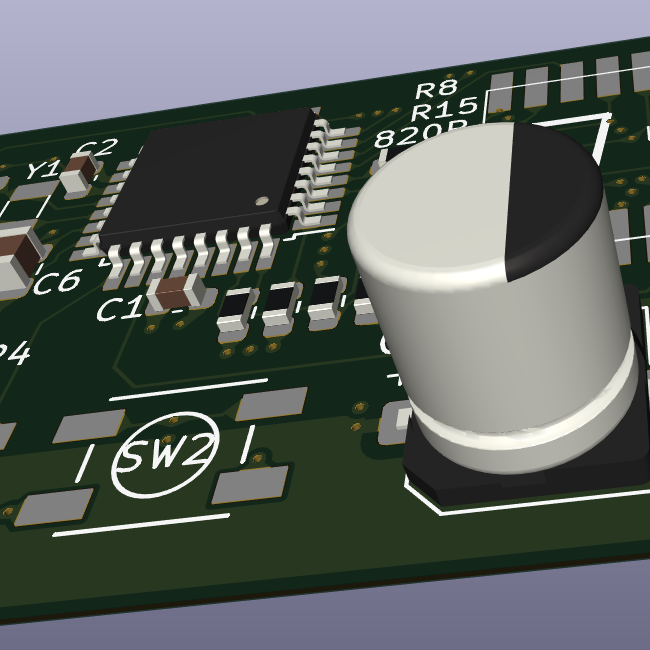
I was reviewing a recent project of mine, comparing the LTSpice simulations vs my real physical circuit, when I noticed that there are effectively two independent ways of measuring “ESR”.
So lets slow down for beginners for a moment. When EEs teach resistors, capacitors, and inductors to students, we are basically lying to you. There’s no “ideal capacitor”. All capacitors exhibit parasitic elements (aka: acts a little bit like a resistor or inductor), and not like the ideal math from the beginner world would imply.
But there’s a 2nd layer to this, and it hits at the core of ESR/Impedance vs Dissipation Factor. Depending on how you test these parasitic elements, the value will change, sometimes dramatically.
Lets look at the 330uF WCAP-ASLI capacitor I chose for my project more closely. https://www.we-online.com/components/products/datasheet/865080145010.pdf

DF is created with one test, while the “Impedance” value here is a separate test. (Note, there is a frequency-dependent component with these parasitics, but according to RedExpert, frequency doesn’t affect us in this particular discussion). https://redexpert.we-online.com/we-redexpert/en/#/redexpert-embedded

Also note: the ESR in this graph has been measured to be under 200mOhm (so yet a 3rd, completely different value to add to our mix!! Hurrah, I’m going to ignore this one, I’ve got enough trouble just talking about the other two “ESR” values already calculated in this topic…)
So DF is supposed to be related to ESR with the formula: ESR = DF / (2 * Pi * Frequency * Capacitance), or ~0.95 Ohms in this case. But… ESR/Impedance has been measured to be 0.34 Ohms, a rather substantial difference. What gives?
I’m going to admit that I’m now entering the realm of ignorance. I don’t know why we have to different tests for what amounts to be an ESR test. But what I can say is that DF is measured at 120Hz, suggesting that the DF is more applicable to 60Hz power-line mains. While Impedance/ESR values are tested at higher-frequencies, suggesting a test more applicable to boost/buck converters or the like.
Since the values / specifications of ESR differ so grossly depending on “how you test for it”, it behooves the EE to not only read these specifications, but understand the tests behind the specifications. So that we can better predict what will happen in reality. I assume that anyone building a full-bridge rectifier at 60Hz power lines (or 120Hz after rectification) will want to use dissipation factor values instead.
In particular: it seems like the Dissipation Factor (and the ESR-calculated-from-dissipation factor) is a strong estimate on the amount of Watts-of-heat generated from a 120Hz power-line (after full-bridge rectification). For some applications, its this heat generation that’s the most important thing to calculate.
But for my purposes, where the capacitor is basically a decoupling / energy storage capacitor, Dissipation Factor (and its associated ESR of 0.97 Ohms) is not a good estimate on the final ripple going into/out of my boost converter. In this case, the Impedance value above (ie: 0.34 Ohms) is a superior estimate to what’s happening in my circuit.
And this is engineering. Understanding not only the specified values, but choosing which value to think about deeper depending on context. The EE-world is full of little contradictions like this.
Leakage resistance also contributes to dissipation factor and the simple formula omits this, that is why ESR calculated from dissipation factor is larger. As you said, if one is more interested in heat generated, dissipation factor is more important (leakage also dissipates power). If interested in the decoupling and filter performance of the capacitor, ESR is more important. And all these depend on temperature and capacitor bias voltage as well :)
Leakage losses is all this crap again though.
The leakage current of 20uA at 6.3V suggests a leakage-resistor of 315,000 Ohms.
EDIT: Hold up, I think I’m miscalculating things. But whatever the parallel resistor is from the DF-based methodology will be very different.

